Universal Serial Bus
1994年首次引入通用串行总线USB,目的是替换各种专用接口,并简化通信设备的配置。 通信行业并没有像USB-IF所预见的那样发展,但是USB引入的各种传输模式使其成为当今使用中最受欢迎的标准之一。 几乎每台现代计算机都支持USB。
简介
尽管USB支持很有吸引力,但650页的USB 2.0规范阻止了一些想学的业余爱好者 (特别如果英语不是他们的主要语言)。 不仅USB 2.0规格很长,而且它是 XHCI 、 EHCI 、 UHCI 和 OHCI 规格的先决条件,这些规格定义了实际的硬件操作系统接口。 此外,USB规范定义了过多的术语,有些术语可以互换使用,并且似乎很难快速理解; 作为冗长的技术文档,来回翻转以阐明令人困惑的术语或概念既不容易也不实用。
这篇文章涵盖的内容
事实是,软件开发人员不需要阅读整个USB 2.0规范; 比如其中有一些章节是特定于硬件开发人员的。 此处提供的信息试图总结第4、5和8至10章的内容。
第11章特定于Hub集线器,对于完整的USB 2.0实现也是必不可少的,可是它几乎与第4、5、8、9和10章的加起来一样长,并且可以被视为特定 (尽管是特殊的) USB设备类别的文档。 因此,第11章在其自己的wiki条目 USB Hubs 中进行了介绍。 即便如此,本文在相关的地方简要讨论了一些与USB集线器有关的概念。
理想情况下,此处的文本将为业余操作系统开发人员开始实现USB支持建立所需的术语和概念的熟悉了解,并且,如果需要,可以轻松地解析USB规范,而不会被信息量所吓倒。 至少,在使用USB相关硬件时,系统程序员应保留USB 2.0规范副本以供参考。
幸运的是,所有必要的文档都是免费提供的 (请参阅 链接)。
这篇文章没有涵盖的内容
请注意,与 VGA 或 PCI 等其他标准不同,USB与系统总线 (以及扩展到操作系统) 的硬件接口无关。 这样的接口由一个或多个 USB主机控制器 提供,并由相应的文档定义。 因此,不应该期望这篇文章讨论细节或代码示例 (如在关于 VGA 或 PCI 的维基条目中发现的那样) 详细说明操作系统如何启动和保持与USB设备的通信。 尽管可以在讨论特定 主机控制器驱动程序 的wiki条目中找到此类信息,但这些wiki条目需要对此处讨论的概念和术语的理解。
Host Controllers
Host Controller 是主机系统的USB接口。 换句话说,系统软件是用主机控制器来与USB设备通信的。
USB 1.0 Host Controllers
英特尔通过其 Universal Host Controller Interface (“'UHCI'”) 将USB 1.0推向市场,而康柏,微软和National Semiconductors则通过其 “'Open Host Controller Interface” (“'OHCI'”) 进行了相同的操作。 当然,这两个接口是不兼容的,更糟糕的是,VIA Technologies也认证了英特尔UHCI标准许可的技术,从而导致这两个标准都能保留下来了。 通常,板载芯片组将包含UHCI实现,而外围卡通常实现OHCI标准 (但这不能绝对保证)。
USB 2.0 Host Controllers
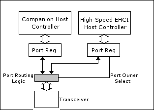
在设计USB 2.0时,USB-IF坚持单一实现。 该单一实现是英特尔的 “增强型主机控制器接口” (“ehci”)。 然而,即使USB 2.0规范要求USB 2.0接口支持USB 1.0设备,这并不意味着EHCI必须支持USB 1.0设备,事实上,它也不支持。 每个EHCI主机控制器都伴随着 (通常是几个) UHCI和/或OHCI主机控制器。 当连接USB 1.0设备时,EHCI只需将控制权移交给 “同伴控制器”。 有关此行为的简单框图实现,请参见图1。 因此,为了支持USB 2.0,系统编程器必须支持所有三个标准。
EHCI主机控制器仅在通过USB 2.0集线器间接连接的情况下处理USB 1.0设备。 在 hubs 部分,以及在 USB Hubs 的wiki条目中,简要讨论和说明处理USB 2.0集线器上连接的USB 1.0设备的细节。 请注意,某些较新的芯片组 (例如Intel 5系列芯片组) 根本没有配套控制器,而是具有所有USB设备都通过的内部 “速率匹配” 集线器。
USB 3.0 Host Controllers
与其前身USB 2.0一样,USB 3.0只有一个主机控制器规格: 英特尔的 “可扩展主机控制器接口”。 然而,与其前身EHCI不同,xHCI控制器可以并且不使用配套控制器就可以与USB 1.0和2.0设备接口。 即使在包含EHCI和xHCI控制器的早期硬件上 (即尚不支持xHCI的操作系统仍然可以至少使用某些USB设备),一般可以将连接到EHCI控制器的端口 “重新路由” 到xHCI控制器,并且EHCI控制器完全禁用。
与以前的版本不同,xHCI的设计具有一定程度的 “转发兼容性”,因此无需设计新的主机控制器接口即可对USB规范进行修订 (例如,USB 3.1和3.2增加了新的速度模式,只需对规范进行较小的更新即可与之匹配。) 不幸的是,这意味着xHCI与之前的控制器只有短暂的相似之处,这使得编写驱动程序具有挑战性。
基本概念和命名法
USB是一种轮询总线,仅仅意味着Host Controller必须初始化所有传输。 不要误以为系统软件必须时刻轮询USB。 而是Host Controller负责轮询总线,并可以对其进行编程,以在总线需要注意时向操作系统发出中断。
USB系统
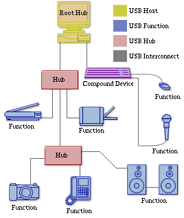
“USB系统” 由三个独立的部分组成: USB device(s), USB interconnect, 和 USB host。 图2展示了一个USB系统。
USB Device(s)
USB devices 被分类为 hub 或 function (不要与程序过程函数混淆)。 HUB提供了额外的附着点,而function则为系统提供了功能。 某些设备可以在一个物理包中实现多种function和嵌入式hub。 这些被称为 compound devices 复合装置 。
Functions
所有function都必须按照USB协议,响应标准操作 (例如配置或重置),并向USB主机描述功能。
有四个速度类别的function:
- Super-speed functions 以高达5 gb/s的速度运行.
- High-speed functions 工作速度高达480 Mb/s.
- Full-speed functions 工作速度高达12 Mb/s。
- Low-speed functions 操作速度高达1.5 Mb/s。
最初的USB规范定义了low-speed低速和full-speed全速设备,而USB 2.0增加了high-speed高速设备,USB 3.0增加了super-speed超高速设备。
Hubs
在high-speed系统中, high-speed hub起着特殊的作用。 由于high-speed Hub与host建立了high-speed传输速率,因此它必须将任何full-或low-speed信号与Host和任何连接的high-speed设备隔离开来。
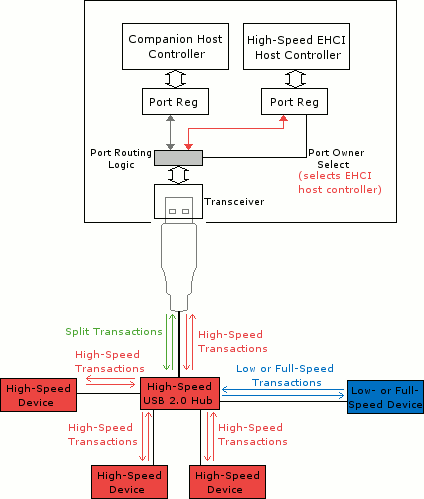
为了更好地理解,请考虑EHCI控制器伴随有一个或多个伴随控制器,如上面的图1所示。 当full-或low-speed设备直接连接到根Hub时,EHCI控制器可以将该特定端口的所有权放弃给配套控制器,如图3所示。 但是,如果高速集线器连接到端口,如图4所示,则EHCI控制器必须保留该端口的所有权,因为它是high-speed设备。 现在假设其他高速设备连接到图4中的high-speed Hub; 显然,EHCI控制器保留了如图5所示的控制。
但是,当full-或low-speed设备连接到图5中的high-speed hub时会发生什么? 如果EHCI控制器放弃端口的所有权,则high-speed设备将不再能够high-speed运行 (如果有的话),如图6所示。 相反,Host控制器和Hub支持一种特殊类型的事务,称为split transaction。 split transaction 仅涉及Host控制器和high-speed hub; 它对任何设备都是透明的。 在图7中表达了使用split-transaction来支持high-speed hub上的low-和full-speed设备的方案。
请注意,某些较新的芯片组 (例如Intel 5系列芯片组) 根本没有配套控制器,而是具有所有USB设备都通过的内部 “速率匹配” 集线器。
USB Interconnect
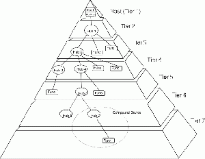
'USB interconnect提供从USB设备到USB主机的连接。 从物理上讲,USB interconnect是分层的星形拓扑。 最多允许七层,根集线器占据第一层。 由于复合设备包含嵌入式集线器,因此不能在第7层中附加复合设备。 图8示出了USB拓扑 (取自USB 2.0规范的图4-1)。
USB Host
一个USB系统只包含一个 USB Host 。 Host通过Host控制器与USB互连接口。 Host包括一个称为 “'root hub'” 的嵌入式hub,该hub提供一个或多个 “attachment points 接入点” 或 “port 端口”。
USB通信流程
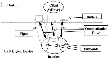
图9表示了USB通信流程的概念,取自USB 2.0规范的图5-10。
Device Endpoints设备端点和Endpoint端点编号
每个USB设备都包含一个端点集合。 每个端点都具有以下特征:
- 总线访问频率/延迟要求
- 带宽要求
- 唯一的设备确定标识符,称为端点号
- 错误处理行为要求
- 端点可以发送或接收的最大数据包大小
- 端点的传输类型
- 相对设备确定的数据传输方向:
- Input 输入 : 从设备到主机
- Output 输出 : 从主机到设备
作为示例,考虑 “多合一” 打印机/扫描仪设备。 这样的设备可以实现用于打印功能的端点号和用于扫描功能的单独的端点号。
尽管端点具有特定的方向,但两个端点可能具有相同的端点编号,但数据传输方向相反。 所有function都实现了端点编号为0的两个这样的端点。 只有端点编号为0的端点可以在设备通电并收到总线复位后立即被访问; 所有其他端点都处于未定义的状态,直到设备被配置。
除了两个所需的端点外,functions还可以根据需要实现其他端点,但存在以下限制:
- 低速functions可能会实现最多两个附加端点。
- 全速和高速设备最多可实现15个额外的输入端点和15个额外的输出端点。 这是USB协议的物理限制,在 Endpoint_Field 下进行了讨论。
端点 Zero
所有USB设备都实现端点编号为0的输入和输出端点。 这些端点统称为 默认 control pipe 。 端点编号为0的端点是特殊的,因为每当设备连接,供电并收到总线重置时,它们都可以访问。
为了向后兼容,即使连接到全速运行的集线器,所有高速功能也必须支持这些端点。 这意味着高速设备必须能够以全速重置,以及以全速成功响应标准请求。 但是,不需要高速设备以全速支持其预期功能。 这允许USB 1.0系统识别USB 2.0设备,并在设备无法全速正常运行时提醒用户
Pipes
管道将主机上的软件 (特别是主机上的缓冲区) 与设备上的端点相关联。
管道通讯方式有两种:
- 流管道 正在传输的数据是无强制结构要求的。 流管道在其通信流中始终是 “单向” 的。
- 消息管道 对正在传输的数据施加一些结构。 消息管道是 “双向”,但是数据可能主要在一个方向上传输。
管道还具有以下属性:
- 关于总线访问和带宽使用的声明
- 传输类型类型
- 关联端点的特征
一个管道中的数据流独立于任何其他管道中的数据流。 配置设备后,大多数管道都可用,但是在USB设备通电并接收到总线重置后,“默认控制管” 始终存在。
默认控制管道
默认控制管 是一种特殊类型的消息管道,一旦设备通电并收到总线重置,它就始终可以访问。 因此,默认控制管道提供了一种识别和配置设备的手段,使得额外的端点 (如果有的话) 可用。
完全识别设备所需的信息与默认控制管道相关联; 此类信息属于以下类别:
- Standard 信息在所有USB设备中都是常见的。
- Class 信息取决于标准信息所标识的USB设备的类别。
- USB Vendor 信息可以被硬件供应商自由使用。
USB传输的基础
大多数USB传输事务由三个数据包组成:
- “令牌包” 指示传输的类型和方向,设备地址和端点号。
- 根据传输的方向,host或function发送一个 data packet (也可能只是表示没有要发送的数据)。
- 接收设备以 “握手包” 进行响应,以指示传输是否成功。
USB支持通过管道进行的四种基本类型的数据传输。 对于任何给定的设备配置,单个管道仅 (并且确切地) 支持一种传输类型。 也就是说,function可以提供一种改变设备实现的端点号的传输类型的手段。
简而言之,四种基本传输类型是:
- 控制传输 提供无损传输,用于配置设备。 因此,所有USB设备必须至少通过默认控制管道支持控制传输。
- 批量数据传输 提供无损,顺序传输,通常用于传输大量数据。
- ““ 中断数据传输 ”” 可提供人工输入设备 (例如鼠标或操纵杆) 通常需要的可靠,有限延迟的传输。
- Isochronous Data Transfers 等时数据传输 ,也称为 Streaming Real-time Transfers 流实时传输,在初始化传输时协商所需的带宽和延迟。 这种传输类型主要用于流音频等应用。 由于对于这种类型的传输,数据传递速率被认为比数据完整性更重要,因此它不提供任何类型的错误检查或纠正机制。
控制传输
控制传输支持配置/命令/状态类型通信流。 host通过设置总线传输事务向function发起控制传输,在该function上建立预期数据传输的详细信息,例如主机是否希望发送或接收数据。 接下来,在适当的方向上发生零个或多个数据传输。 最后,还会有一个从function到host的状态传输指示传输是否成功。
显然,控制传输遵循USB定义的结构,因此控制传输只能通过消息管道进行也就不足为奇了。
function和host都不能保证任何特定的延迟或带宽来进行控制传输。
最大数据有效负载大小
用于控制传输的端点指定它可以接受或传输到总线的 “最大数据有效负载大小”。 允许的最大数据有效载荷大小取决于设备的速度:
- 高速设备端点只能选择最大数据有效负载大小为64字节。
- 全速设备端点可以选择最大数据有效负载大小为8、16、32或64字节。
- 低速设备端点只能选择8字节的最大数据有效负载大小。
除非当前数据有效负载小于最大数据有效负载大小,否则控制传输始终会将数据有效负载填充满最大数据有效负载大小。 也就是说,如果端点具有64字节的最大数据有效载荷大小,并且控制传输打算发送100字节,则第一数据有效载荷必须包含64字节且不少于64字节。 剩余的36个字节在第二个有效负载中传输,不需要填充到64个字节。 当host接收到小于最大数据有效载荷的数据有效载荷时,host可以认为传输完成。
一个SETUP设置传输的数据有效负载始终为8个字节,因此可由任何USB设备的端点接收。 因此,主机可以在配置期间从新连接的全速设备查询适当的描述符,以便确定任何端点的最大数据有效载荷大小; 然后,主机可以针对任何将来的传输坚持该最大值。
传输错误
数据太多
当从主机传输到设备时,如果主机发送的数据比在设置传输期间协商的数据多 (即,设备接收的数据比它预期的要多; 具体地说,当设备预设时,主机不前进到STATUS状态阶段),则设备端点停止管道。
当从设备传输到主机时,如果设备发送的数据多于在设置事务期间协商的数据 (即,主机接收到额外的数据有效载荷,或者最终的数据有效载荷大于其应有的数据),则主机将其视为错误并中止传输。
总线错误
在总线错误或异常的情况下,端点可能会在控制传输过程中接收设置数据包。 在这种情况下,端点必须中止当前传输并处理意外的设置数据包。 这种行为对主机应该是完全透明的; 主机既不应该期望也不应该利用这种行为。
Halt Conditions
控制端点可以在接收到SETUP设置数据包时从Halt Condition暂停条件中恢复。 如果端点未从设置数据包中恢复,则可能需要通过其他管道将其恢复。 如果端点编号为0的端点无法通过设置数据包恢复,则主机应认为设备需重置。
批量数据传输
具有批量传输类型的管道提供:
- 在带宽可用的基础上访问USB
- 遇到偶尔交付失败的传输进行重试
- 保证数据完整性,但无保证带宽
主机控制器赋予批量数据传输低优先级; 它们通常仅在带宽可用时才被处理,但是软件可能不会假设控制传输将在批量传输之前被处理。 如果多个批量传输在进行中,则主机控制器可以根据与实现相关的策略开始在总线上以移动的方式进行批量传输。 系统软件可以改变可用于批量传输到特定端点的总线时间。
USB不会对批量传输的数据内容施加任何结构; 因此,批量传输是通过流管进行的。
最大数据有效载荷大小
用于批量数据传输的端点指定它可以接受或传输到总线的 “最大数据有效负载大小”。 允许的最大数据有效载荷大小取决于设备的速度:
- 高速设备端点只能选择512字节的最大数据有效负载大小。
- 全速设备端点可以选择最大数据有效负载大小为8、16、32或64字节。
- 低速设备可能无法实现批量端点。
与前面控制传输一样,批量传输端点必须传输该端点的最大数据有效载荷大小的数据有效载荷,但特定传输中的最后一个数据有效载荷除外。 最后一个数据有效负载不需要 (也不应该) 填充到最大数据有效负载大小。
当端点传输的数据与预期的一样多,端点传输的数据有效载荷大小小于端点的最大数据有效载荷大小的数据包,或者端点传输的长度为零的数据包时,批量传输被认为是完成的。
传输错误
如果传输的数据有效负载大于预期,则应通过同一管道中止传输以及任何未决的批量传输。
批量数据传输使用数据切换位来检测错误,并提供必要的同步以从错误中恢复。 如果检测到halt condition,则应停用所有剩余的批量转移。 halt condition通过单独的控制管道恢复。
中断数据传输
中断数据传输保证了任何数据传输的最长服务时间。(译者注:这里值至少在一段时间内再获得一次数据传输,这个时间相对于人工输入设备这类设备来说会很短,所以感觉和普通中断一样) 即使发生传输故障,也会在下一个周期重新传输数据。 因此,中断数据传输对于不经常发送数据的设备是理想的选择,但是当它们发送数据时,它们需要及时传输以及数据完整性; 大多数人工输入设备都有这些要求。
中断数据传输由流管道执行,因此不需要遵循任何USB数据结构。
最大数据有效载荷大小
用于中断数据传输的端点指定它可以接受或传输到总线的 “最大数据有效负载大小”。 允许的最大数据有效载荷大小取决于设备的速度:
- 高速设备端点可以选择最多1024字节的最大数据有效负载大小。
- 全速设备端点可以选择最多64字节的最大数据有效负载大小。
- 低速设备端点可以选择最多8个字节的最大数据有效负载大小。
此外,高速,高带宽端点可以指定每个microframe微帧需要两次或三次传输事务。 error
请注意,中断数据传输的最大数据有效负载大小比控制或批量数据传输允许更大的粒度。 这样用于高速设备的中断数据传输端点可以是从0到1024的任何整数。 中断传输端点的最大数据有效负载大小在设备配置的生命周期内保持恒定。
与控制和批量数据传输一样,中断传输端点的有效载荷大小必须是该端点的最大数据有效载荷大小,特定传输中的最后一个数据有效载荷除外。 最后一个数据有效负载不需要 (也不应该) 填充到最大数据有效负载大小。
当端点传输的数据与预期的一样多,端点传输的数据有效载荷大小小于端点的最大数据有效载荷大小的数据包,或者端点传输的是零长度的数据包时,中断传输被认为是完成的。
传输错误
如果传输的数据有效载荷大于预期,则应中止传输,并且管道将停止任何将来的中断传输,直到确认并纠正错误为止。
中断数据传输可以使用两种数据切换位方案之一来确保成功的数据传输。 需要更高通放的设备可以选择切换每次传输,而不是与主机进行握手。 与成功传输后 (握手后) 切换位的替代方法相比,此方法更容易出错。
如果检测到halt condition,则应停用任何挂起的中断传输。 halt condition通过单独的控制管道恢复。
等时数据传输
等时数据传输与中断传输相似,因为它们保证任何传输的最长服务时间,但是等时数据传输不能确保数据完整性。 当准备将数据传输到等时端点或从等时端点传输时,数据始终以恒定速率传输。
通过等时管道传输的数据不需要任何特定的结构,因此等时管道是流管。
最大数据有效载荷大小
用于等时数据传输的端点指定它可以接受或传输到总线的 “最大数据有效负载大小”。允许的最大数据有效载荷大小取决于设备的速度:
- 高速设备端点可以选择最多1024字节的最大数据有效负载大小。
- 全速设备端点可以选择最多1023字节的最大数据有效负载大小。
- 低速设备可能无法实现等时端点。
与中断端点一样,等时端点可以指定具有字节粒度的最大数据有效负载大小。 与中断端点一样,高速,高带宽等时端点可以指定每个微帧是否需要两次或三次传输。
与任何其他传输类型不同,等时传输可以在任何传输期间传输小于最大数据有效载荷大小的任意数量的数据。
传输错误
等时传输适用于数据传输速率比数据完整性更重要的设备。 因此,等时传输没有握手应答过程,因此不能停滞传输。 但是等时传输的执行者知道是否发生错误以及可能丢失了多少数据仍然很重要。 USB协议提供了几种机制来检测同步传输中的数据传输错误,这些机制将在后面讨论。 确认丢失的数据量得取决于具体实现。 由主机上的软件或function上的固件来实现任意某种类型的数据损坏检测/纠正。
高级USB概念
本节中的主题以先前讨论的主题为基础。 本节中的信息提供了有关USB系统的一些有用的较底层的详细信息。
总线接入时间的分布
帧和微帧
为了确保主机和function之间的同步,USB将总线时间划分为固定长度的段。 对于低速或全速总线,USB将总线时间分为1毫秒单位,称为 “Frame 帧”。 对于高速总线,USB将总线时间分为125微秒单位,称为 “microframes 微帧”。
请注意,帧和微帧并不共存于一条总线上; 低速和全速总线使用帧,但在开发高速总线时,较短的帧是必要的,因为显著更高的信令比特率对host和function之间的同步的较小变化更敏感。
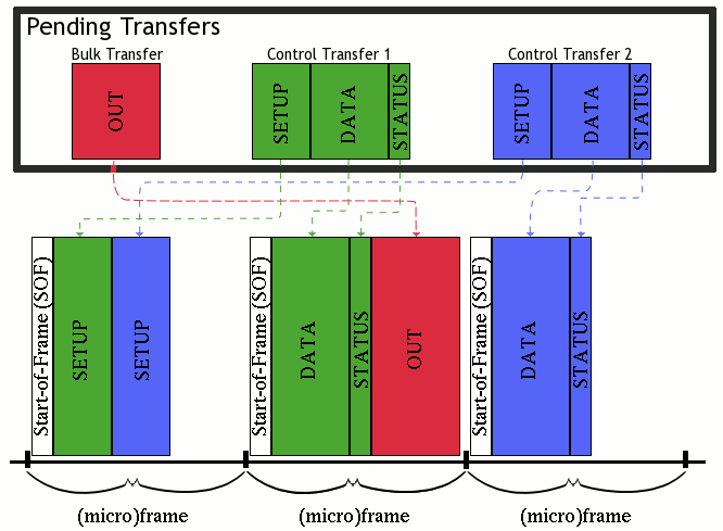
帧和微帧主要是物理层细节,不应与任何先前的概念混淆。 帧和微帧不对应于任何数据包或事务; 实际上,多次传输通常在一个 (微) 帧的时间间隙发生。 主机控制器在每个 (微) 帧的开头发出一个 “帧开始” (“sof”) 数据包。 (微) 帧的剩余部分可供主机控制器执行数据传输。 如果无法在同一 (微) 帧中完成传输,则可能无法完成传输 (因为否则下一个SOF数据包将中断事务)。
重要的是要认识到,主机控制器可以重新安排传输以更好地利用可用带宽。 当然,通过同一管道的两个传输必须以正确的顺序发生,但是两个独立的传输的切换可以由主机控制器自行决定重新排序。 假设有一个待处理的批量传输和两个待处理的控制传输。 如图11所示,主机可能会重新排序总线上的传输。
总线时间配给
对于全/低速总线上的帧分配,以及对于高速总线上的微帧分配,都有单独的规则。
对于全速或低速总线:
- 如果控制传输需要的帧少于10%,则剩余的总线时间可用于支持批量传输
- 如果控制传输需要时间比预留的时间多,而且中断或等时传输未使用的额外帧时间,则主机控制器可以将其他控制传输移动到总线上。
- 为定期 (等时和中断) 传输分配的帧不超过90%。
- 对于特定的等时端点,主机不得在单个帧中发出超过一次传输。
对于高速总线:
- 如果控制传输需要的微帧少于20%,则剩余的总线时间可用于支持批量传输。
- 如果控制传输需要时间比保留时间更多,但中断或等时传输不需要额外微帧时间,则主机控制器可以将其他控制传输移动到总线上。
- 为定期 (等时和中断) 传输分配的帧不超过80%。
- 主机不得在单个微帧中针对特定的等时端点发出超过1次传输,除非它是高速,高带宽的端点。
- 分割传输总线访问时间是从保证定期传输的微帧80% 分配的。
高速、高带宽端点
需要高带宽的高速中断或等时端点可能会指定它们在单个 (微) 帧中最多支持三次传输。 在这种情况下,除特定 (微) 帧中的最后一次传输外,所有传输都必须具有该端点的最大数据有效载荷大小的数据有效载荷。
主机控制器从不重试具有等时端点的传输。 如果具有高速、高带宽中断端点的传输失败,如果尚未达到每个 (微) 帧的最大传输数,则主机控制器可以在同一 (微) 帧期间重试该传输。 否则,传输将在下一期重试。
支持等时传输
回想一下,等时传输发生在流管道上,流管道提供单向数据传输。 对于一个管道,在称为 “源、上游 source” 上产生数据,而在另一端称为 “下游 sink”上传递数据。
实现等时端点的设备要求数据以一定的速率从源传输到接收器,有时是在大的有效载荷 (例如,流音频或视频) 中。 本节讨论USB如何满足这些要求。
同步
由于特定于应用程序的采样率,不同的硬件时钟设计,操作系统中的调度策略,甚至物理异常,主机和同步设备可能会脱离同步。 因此,需要特别考虑来保持同步。 等时端点指定以下三种同步类型之一。
异步端点
Asynchronous 异步端点无法同步到SOF数据包频率 (全速端点为1ms周期,高速端点为125微秒周期)。 这些端点具有: 一组一个或多个固定数据采样率,或连续可编程数据速率。设备必须以某种方式 (由设备的类而不是USB规范定义) 报告异步端点的可编程性; 如果数据速率是可编程的,则必须在同步端点初始化期间由主机设置。
异步源端点通过每个 (微) 帧产生的样本数来暗示其数据速率。 异步接收器端点必须向源端点提供显式反馈。 当源端点是主机时,设备驱动程序有责任正确处理显式反馈。 该反馈允许主机和设备对数据速率进行轻微调整,以补偿任何时钟漂移。
同步端点
“同步” 端点必须将其数据传输同步到SOF数据包频率 (全速端点为1ms周期,高速端点为125微秒周期)。 这些端点具有一组一个或多个固定数据采样率,或连续可编程数据速率。 设备必须以某种方式 (由设备的类而不是USB规范定义) 报告同步端点的可编程性; 如果数据速率是可编程的,则必须在同步端点初始化期间由主机设置。
自适应端点
Adaptive' 端点可以在其指定的工作范围内以任何速率来源或接收数据。 这些端点可以具有围绕特定数据速率的操作范围,它可以具有有限的一组数据速率范围,或者它可以在若干可编程或自动检测数据速率之间进行选择。 设备必须以某种方式 (由设备的类别而不是USB规范定义) 报告自适应端点的可编程性; 与以前的同步类型不同,自适应端点可以在操作期间调整其瞬时数据速率。
自适应接收器端点像异步端点一样为源提供显式反馈。
处理错误
不为等时传输执行握手,从而消除了确认数据包的带宽开销。 与其他传输类型不同,等时端点的应用负责任何错误检测和处理。 尽管继续传递流数据而不是重传丢失的数据包可能更重要,但是等时端点的应用程序通常仍然需要知道流中确实发生了错误。
USB协议强调了以下主机或设备检测等时流中的错误的可能方法:
- 高速,高带宽等时传输使用数据PID序列 (数据位切换),等时接收器可以确定在接收到无效数据PID序列时丢失了数据包。
- 主机控制器和设备都可以在总线上看到SOF数据包。 如果SOF数据包是针对预期携带等时端点的周期性数据的 (微) 帧发出的,但该数据不被传输,则硬件可以确定丢失了分组。
- 该协议提供CRC保护,以确保数据没有损坏。
- 如果端点看到令牌数据包,但在总线事务超时时间内没有看到关联的数据包,则该数据包无法传输。
一旦应用程序意识到流中有错误,就由应用程序决定下一步的行动方案。
USB协议
数据包
数据传输的原子单位是一个数据包。 数据包是一堆有组织的数据,通常包含三个元素:
- 控制信息 (例如源,目的地,数据长度)
- 特定于用户/应用程序的数据
- 错误检测和校正位
同步字段
USB规范中的数据包图中省略了同步字段,通常是USB上用于程序员的其他材料。 在这里,我将简要描述同步字段的语义,因为USB源经常引用同步字段,这可能会使读者感到困惑。 但是,为清楚起见,系统程序员 (可能还有大多数USB设备固件开发人员) 不需要了解同步字段。
所有USB数据包都以同步字段开头,毫不奇怪,该字段用作接收器和发送器之间的同步机制。 同步字段分别由6或30个交替位组成,分别用于低速和全速或高速总线。 同步字段的最后两位相等 (且低)。 高速集线器最多可能会丢弃同步字段的4位,因此接收设备可能看不到整个字段,但是最后的两位是设备所需的全部,以准确识别同步字段的结束位置,并且有用的数据开始。
数据包标识符字段
“” 数据包标识符 “” (“pid”) 立即跟随同步字段。 总共有17个定义的PID (包括0000b的PID,保留),因此PID需要4位才能编码。 如果总线上的错误更改了PID字段 (例如,将OUT PID更改为IN PID),则结果可能是从意外行为到大量数据丢失的任何结果。 由于PID完整性的重要性,PID字段为8位宽。 最后4位只是补充前4位,这提供了一种确定总线上的错误是否改变了PID字段的方法。 PID字段如下所示。
| PID0 | PID1 | PID2 | PID3 | PID0 | PID1 | PID2 | PID3 |
PID代码分为4组,它们共享相同的两个最低有效位。 USB 2.0定义下表中的pid。
| PID Type | PID Name | PID [3:0] | Description |
|---|---|---|---|
| Token | OUT | 0001b | The packet describes a host-to-function transaction. |
| IN | 1001b | The packet describes a function-to-host transaction. | |
| SOF | 0101b | The packet marks the start of frame and specifies the frame number. | |
| SETUP | 1101b | Packet describes a SETUP transaction from the host to the function via a control pipe. | |
| Data | DATA0
|
0011b | This packet is an even data packet. |
| DATA1 | 1011b | This packet is an odd data packet | |
| DATA2 | 0111b | This packet is only used in high-speed, high-bandwidth isochronous transfers. | |
| MDATA | 1111b | This packet is only used in split transactions, or high-speed, high-bandwidth isochronous transfers. | |
| Handshake | ACK | 0010b | This packet acknowledges the successful receipt of a data packet. |
| NAK | 1010b | This packet indicates that data is not ready to be transmitted yet. | |
| STALL | 1110b | This packet indicates that the endpoint has halted, or a control pipe does not support a certain request. | |
| NYET | 0110b | The receiver has not yet responded, or the host should begin sending PING packets. | |
| Special | PRE | 1100b | This packet is a host-issued preamble for a split-transaction. |
| ERR | 1100b | This packet is a handshake response that a split transaction error occurred. Note that this PID is identical to the PID for a PRE packet. | |
| SPLIT | 1000b | This packet supports split transactions between the host and a high-speed hub. | |
| PING | 0100b | This packet is used for flow-control in high-speed control and bulk transfers. | |
| Reserved | 0000b | This is a reserved PID and must not be used. |
地址字段
地址字段选择特定function上的特定端点。 自然,定义了两个这样的字段: 地址字段和端点字段。 所有设备都必须完全解码这些字段; 必须忽略任一字段 (包括指定尚未初始化的端点字段) 的不匹配。
地址字段
地址字段是为以下pid指定的:
- IN
- SETUP
- OUT
- PING
- SPLIT
地址字段为7位宽,如下所示。 每个可能的值只能表示单个函数。 地址零保留为 默认地址 ,并且不能分配给任何函数。 在重置和加电时,所有功能都必须响应默认地址,直到主机为功能分配特定地址为止。 因此,一个主机控制器可以同时支持多达127个设备。
| Addr0 | Addr1 | Addr2 | Addr3 | Addr4 | Addr5 | Addr6 |
端点字段
endpoint字段是为以下pid指定的:
- IN
- SETUP
- OUT
- PING
端点字段为4位宽,如下所示。 所有功能必须至少支持端点编号0 (默认控制管道)。 低速功能可能仅实现2个额外的管道,而全速和高速设备仅受端点字段宽度的限制。 换句话说,端点字段的宽度是全速和高速设备仅限于实现多达15个额外的In端点和15个额外的OUT端点的原因,如上面 设备端点和端点编号 下所述。
| Endp0 | Endp1 | Endp2 | Endp3 |
数据字段
数据字段的范围可以从0到1,024字节,并且必须是整数个字节。 数据字节首先发送最低有效位。
循环冗余校验
循环冗余校验 (CRC) 保护所有非PID字段,并为所有单位和双位错误提供100% 覆盖。 为每个令牌字段以及数据字段提供了crc。 这为主机或设备提供了一种机制来识别和纠正或忽略损坏的字段,或者在大多数情况下,整个损坏的数据包。
握手
支持流控制的传输类型返回握手以指示:
- 成功接收数据
- 命令接受或拒绝
- 流控制
- 暂停条件
握手总是在事务的握手阶段返回,但也可能在数据阶段 (代替预期的数据包) 返回。 为了最好地理解某个握手响应,理解每个握手包类型意味着什么以及可以发出每个握手响应的条件是有用的。 因此,这一部分被分割了。
握手包
所有握手数据包类型都在 数据包标识符字段 中简要列出。 本节将更详细地讨论这些数据包类型。
ACK
| May be issued by... | For these transactions |
|---|---|
| Host | IN |
| Function | OUT |
| SETUP | |
| PING |
发出ACK握手以传达成功接收到数据包而没有数据字段上的任何位填充或CRC错误,并且PID字段未损坏。
当接收器的序列位与接收到的数据包的序列位匹配 (并且可以接受数据) 时,可能会发出ACK数据包,但是,当接收器的序列位与接收到的数据包的序列位不匹配 (并且无法接受数据) 时,也可以发出ACK数据包。 这似乎与直觉相反,但是在讨论数据切换的部分中,推理将变得清晰。
NAK
| May be issued by... | For these transactions |
|---|---|
| Function | IN |
| OUT | |
| PING |
NAK握手包一般用于流控制,以指示某个功能暂时无法传输或接收数据。 主机从不向设备发出NAK握手包。
当function无法接收数据 (通常是因为函数的内部缓冲区当前已满) 时,函数在OUT事务后将NAK握手数据包返回给主机。此响应不是错误,而是指示主机应稍后重试传输,从而允许函数时间处理当前在其缓冲区中的数据。
function在IN事务的数据阶段将NAK握手数据包返回给主机,以指示该function没有任何数据要传输。
STALL
| May be issued by... | For these transactions |
|---|---|
| Function | IN |
| OUT | |
| PING |
一个function使用STALL失速握手数据包来指示它无法传输或接收数据。 除了默认控制管道外,在设备发出停滞握手数据包后,函数的所有端点都处于未定义状态。 主机绝不能发出STALL握手包。
通常,失速握手表示功能性失速。 设置了端点的 “暂停功能” (将在 “USB框架” 下覆盖) 时,会发生 “功能stall”。 在这种情况下,需要通过默认控制管道进行主机干预,以清除暂停的端点的 “暂停功能”。
在控制传输的设置或数据阶段,该函数通常会返回停滞握手。 这称为 “protocol stall 协议失速”,当主机发出下一个设置事务时会解决。
| May be issued by... | For these transactions |
|---|---|
| Hub | SPLIT |
| Function | OUT |
NYET
可以通过作为PING协议的一部分的功能来发出NYET数据包。
集线器可以响应于在低速/全速总线上尚未完成的拆分事务而发出NYET握手数据包。
| May be issued by... | For these transactions |
|---|---|
| Hub | SPLIT |
ERR
作为拆分传输协议的一部分,集线器可能会发出特殊的错误握手数据包,以在低速/全速总线上报告错误。
Function/Host 响应情况
This section describes the functional circumstances that cause the host or a function to issue an expected response, no response, or certain handshake packet responses. The tables in this section are taken and slightly modified for clarity from the USB 2.0 specifications, section 8.4.6. Dashes denote a "don't care."
Function Response to IN Transactions
| Token received corrupted | Function Tx endpoint halt feature | Function can transmit data | Action taken by function |
|---|---|---|---|
| Yes | - | - | Return no response |
| No | Set | - | Issue STALL handshake |
| No | Not Set | No | Issue NAK handshake |
| No | Not Set | Yes | Issue data packet |
Host Response to IN Transactions
| Data packet corrupted | Host can accept data | Action taken by host | Handshake returned by host |
|---|---|---|---|
| Yes | - | Discard Data | Return no response |
| No | No | Discard Data | Return no response |
| No | Yes | Accept Data | Issue ACK handshake |
Function Response to OUT Transactions
| Data packet corrupted | Receiver halt feature | Sequence bits match | Function can accept data | Action taken by function |
|---|---|---|---|---|
| Yes | - | - | - | Return no response |
| No | Set | - | - | Issue STALL handshake |
| No | Not Set | No | - | Issue ACK handshake |
| No | Not Set | Yes | Yes | Issue ACK handshake |
| No | Not Set | Yes | No | Issue NAK handshake |
Function Response to SETUP Transactions
A function must always accept data in a SETUP transaction, and must never issue a STALL or NAK handshake in response. All non-control endpoints must simply ignore any SETUP transaction addressed to that endpoint. This allows SETUP transactions to function as a (re)synchronization mechanism between the host and a function's control endpoint.
PING事务协议
考虑一个USB大容量存储设备。 在从主机到函数的传输过程中,函数的缓冲区填充了待提交给物理介质的数据。 当function的缓冲区已满时,function不能接受新数据,直到提交了一些缓冲区,所以如果主机继续发送传输,function必须 NAK 它们。
此OUT/NAK模型的问题是,函数必须等待OUT事务的握手阶段,然后才能使用NAK进行响应。 由于握手阶段发生在数据阶段之后,这可能会浪费大量带宽。 低速和全速总线都有这个问题,但是USB 2.0规范引入了高速总线的PING事务协议。
PING事务协议非常简单。 当主机希望发送数据时,主机向function发出PING传输,而不是OUT事务。 该函数以NAK响应以指示其尚未准备好接收数据 (具体地说,该function的缓冲区无法容纳端点的最大数据有效载荷量的数据),或以ACK指示主机可能开始发送数据。
USB 2.0框架允许端点根据微帧指定一个间隔,该间隔是主机在向端点发出另一个PING分组之前应等待的微帧量。 但是,在发出下一个PING数据包之前,不需要主机等待此间隔。
在从主机到功能的高速控制或批量传输期间,当OUT事务导致函数的可用缓冲区空间下降到端点的最大数据有效负载以下时,该函数会使用NYET握手数据包进行响应。 这表明主机应该开始发出PING数据包,而不是额外的OUT事务。
数据切换同步
在传输过程中,主机和功能必须保持同步。 保持同步的能力意味着主机或功能可以检测同步何时丢失,并且在大多数情况下,可以重新同步。
每个端点在内部 (在函数的硬件中) 维护一个数据切换位,也称为数据序列位。 主机还为与其通信的每个端点维护一个数据切换位。 发送器上的数据切换位的状态由发送器使用 数据PID 来指示。
当接收器能够接受数据时,它将切换其数据序列位,并且它接收到带有预期 数据PID 的无错误数据包。 仅在接收到有效的ACK握手时,发送方才切换其数据序列位。 此数据切换方案要求发送方和接收方在事务开始时同步其数据切换位。
根据所使用的传输类型,数据切换同步的工作方式不同:
- 控制传输使用设置数据包将端点的数据切换位初始化为0。
- 中断和批量端点在任何配置事件时将其数据切换位初始化为0。
- 同步传输不执行握手,因此不支持数据切换同步。
- 高速,高带宽等时传输确实支持微帧内的数据排序。
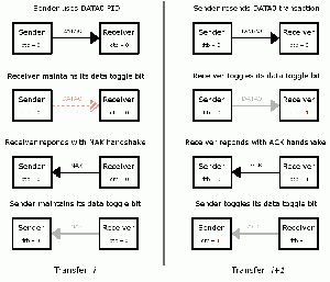
本节的其余部分说明了发送和接收设备如何在不同的传输场景中各自管理其数据切换位。 黑色箭头表示USB上预期的数据传输。 灰色箭头表示预期的数据传输没有错误地完成。 红色不连续箭头表示预期数据在传输过程中已损坏或完全无法传输。
成功传输
图12示出了成功的数据传输。 两个设备在传输i的开始时都将数据切换位设置为0。 相应地,发送设备发出数据分组之后的data0pid。 接收设备成功读取DATA0 PID以及数据包。 由于接收器的数据切换位与DATA0 PID匹配,并且在传输剩余数据时没有错误,因此接收器将其数据切换位切换为1,并发出ACK握手响应。 发送方接收ACK握手没有错误,因此将其数据切换位切换为1。
假设下一次传输也没有错误地发生,唯一的区别是使用DATA1 PID而不是DATA0,并且发送和接收设备在相同的阶段将其数据切换位从1切换到0在先前传输中相同的位切换到1。
数据传输失败或损坏
图13示出了故障或损坏的数据传输。 两个设备在传输i的开始时都将数据切换位设置为0。 相应地,发送设备发出数据分组之后的data0pid。 接收设备要么看不到数据包,要么读取损坏的数据包。 接收器保持其数据切换位并发出NAK握手。 发送方成功看到NAK握手,因此不会切换其数据切换位。
在下一次传输开始时,发送和接收设备都具有仍设置为0的数据切换位。 假设此传输成功完成,则如上文所述,在 成功传输 下进行。
ACK握手失败或损坏
图14说明了失败或损坏的ACK握手。 两个设备在传输i的开始时都将数据切换位设置为0。 相应地,发送设备发出数据分组之后的data0pid。 接收设备成功读取DATA0 PID以及数据包。 由于接收器的数据切换位与DATA0 PID匹配,并且在传输剩余数据时没有错误,因此接收器将其数据切换位切换为1,并发出ACK握手响应。 发送方没有接收或接收到损坏的ACK响应,因此丢弃数据包而不修改其数据切换位。
此时,发送设备的数据切换位仍为0,接收设备的数据切换位已设置为1。 发送者在没有看到传输i的有效ACK响应的情况下,重新尝试传输i。 数据切换位为0时,发送方发出DATA0 PID,后跟数据包。 接收设备成功读取DATA0 PID以及数据包。 由于接收器的数据切换位与DATA0 PID不匹配,因此接收器将其数据切换位值保持为1,并发出ACK握手响应。 发送方接收ACK响应没有错误,因此将其数据切换位切换为1。
假设下一次传输没有错误地发生,它以两个设备的数据切换位设置为1开始,并以它们在传输的适当阶段切换到0结束。
重新审视USB传输
自从 USB传输的基础知识 以来,已经引入了很多信息,并且很容易迷失在细节中。 即使对四种类型的USB传输有了很好的理解,通常也很难从USB协议的复杂性推断为对所有内容如何组合在一起的理解。 由于这些原因,本节旨在通过重新讨论自首次讨论以来所涵盖的所有信息的四种转移类型,来明确和隐含地澄清一些可能令人困惑的概念。
忧心忡忡的读者可能已经注意到,诸如设置和数据之类的一些术语既用于引用 数据包标识符,又用于引用事务类型。 这个维基条目很可能是第一个也是唯一的USB信息来源,需要一点时间来具体区分两者。
在 USB传输的基础知识 下,USB交易仅被简要提及,如下所示:
大多数USB事务由三个数据包组成:
* “令牌包” 指示交易的类型和方向,设备地址以及
端点号。
* Depending on the direction of the transaction, either the host or the function sends a data packet
  (which may simply indicate that there is no data to send).
* The receiving device responds with a handshake packet to indicate if the transfer was successful.
然后,在 Packets 下,一个数据包被描述为 “数据传输的原子单元”。
如果一个包是一个原子,那么一个交易将是一个分子。 也就是说,一个事务是由若干个分组按特定顺序组成的,组成一个事务的分组不能被重新排序或分离,仍然产生相同的事务。 事务通常以其令牌数据包 (或其 “特殊” 数据包,在PING或拆分的情况下,因为这些特殊数据包与令牌数据包起着相同的作用) 来命名,但通常将入或出事务统称为数据事务。 在示例中,包含数据阶段的事务通常通过将0、1、2或M附加到名称或将其添加到括号中 (例如,SETUP(0) 或SETUP0、OUT1或OUT(1)) 来指示使用的数据PID的类型。
图15中描绘了单个设置事务的示例。此事务包含典型的三个数据包。 令牌数据包具有设置PID,数据包具有DATA0 PID (回想一下,设置数据包将函数和主机的数据切换位初始化为0),握手响应具有ACK PID。
转账是由交易组成的。 交易可能不会在传输中重新排序,但是,如 Frames and Microframes 中所讨论的,特定传输的交易可能会或可能不会以连续的方式通过总线发送。 本节的其余部分着眼于四种转移类型中涉及的交易。
控制权转移
控制转移是唯一使用设置事务的转移。控制权转移最多分为三个阶段:
- 设置阶段仅由设置事务组成
- 数据阶段是可选的。 如果使用,它可以包含一个或多个IN事务,或者一个或多个OUT事务。 这些入或出事务中的第一个使用DATA1 PID。 第二个 (如果存在) 使用DATA0 PID,第三个DATA1,依此类推。
- 状态阶段由单个IN或单个OUT事务组成,必须使用DATA1 PID。 如果存在数据阶段,则状态阶段使用与数据阶段相反的事务类型 (即,如果数据阶段由一个或多个执行事务组成,则状态阶段由单个事务组成,反之亦然)。 当数据阶段被省略时,状态阶段使用单个事务。
图16取自USB 2.0规范的图8-37,并且示出了用于控制读和写序列的事务顺序、数据序列位值和数据PID类型。
批量和中断传输
在USB协议的上下文中,批量传输和中断传输之间的唯一区别是,批量传输在高速运行时支持 PING事务协议。 请注意,在一般情况下,这两种传输类型也不同,因为它们由主机进行不同的调度 (请参阅 总线时间配给)。
所有批量和中断端点在一个方向上传输。 在任何配置事件之后,这些端点的数据切换位被初始化为零。 图17取自USB 2.0规范的图8-35,并示出了IN和OUT端点的批量和中断事务。 请注意,即使该图仅提及批量读取和批量写入,USB 2.0规范在中断事务中引用了8.5.4节中的相同图。
等时传输
等时转移是交易不具有握手阶段的唯一转移类型。 同步传输应仅使用DATA0 pid,但是即使同步传输不使用数据同步位机制,主机控制器也必须支持DATA1 pid。
高速、高带宽等时传输
高速,高带宽等时传输是等时传输的一种特殊情况,其中在一个微帧中最多可能发生3个事务。 作为一种特定类型的同步传输,高速,高带宽的同步传输省略了其交易的握手阶段。 由于在一个微帧,高速,高带宽等时传输中最多可能发生3个事务,因此有必要像其他传输类型一样使用数据排序机制。
USB 2.0确实为高速、高带宽同步传输实现了数据排序机制,但它的工作方式与其他传输类型略有不同。 实际上,根据端点是In还是OUT高速高带宽同步端点,数据排序的工作方式不同。
对于高速、高带宽等时端点,数据排序如图18所示,其取自USB 2.0规范的图5-11。 微帧中的最后一个传输始终使用DATA0 PID。 微帧中的倒数第二个事务使用DATA1 PID,微帧中的倒数第三个事务始终使用DATA2 PID。
对于高速、高带宽等时端点,数据排序如图19所示,其取自USB 2.0规范的图5-12。 除了最后一个事务外,所有事务都使用MDATA PID。 最后一个事务使用DATA0、DATA1或DATA2 PID,具体取决于在微帧期间打算发生多少事务。 如果要进行一个事务,则它也是最后一个事务,并使用DATA0 PID。 如果要进行两个事务,则最后一个事务使用DATA1 PID。 如果要进行三个事务,则最后一个事务使用DATA2 PID。
USB设备框架
USB设备框架是使USB支持如此吸引人的东西。 当然,传输类型和USB协议是精心设计的,但是USB设备框架定义了所有设备必须支持的标准设备状态,以及标准请求和响应,其允许主机检索关于设备的足够多的信息以确定正确的设备驱动程序并报告关于设备的信息,即使正确的设备驱动程序不可用 (例如,制造商的名称、产品的名称等)。
Functions, Configurations, Interfaces, and Endpoints
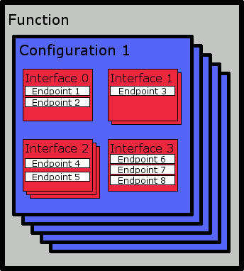
所有USB设备或功能都具有至少一个配置,并且每个配置都具有至少一个接口。 接口可以定义零个或多个端点。 这种关系如图20所示。
尽管配置描述符从配置描述符零开始顺序地寻址,但每个配置都指定了一个唯一的 (在函数的范围内),即none-zero配置值。 “配置值” 是主机需要知道的,以便将特定配置应用于设备。 当请求设备的当前配置时,返回值零表示该设备未配置,因此处于地址状态。
“接口” 定义了一组端点的功能使用,并可能暗示可以通过默认控制管道执行某些特定于类的请求。 因此,接口不一定需要定义任何额外的端点。 没有接口可以定义端点零的功能使用。
每个接口在配置范围内描述了一组唯一的端点。 但是,接口可以提供一个或多个 “替代设置”,这些设置可能对同一组端点具有不同的定义。 当主机为接口选择替代设置时,将使用替代设置的定义,而不是同一接口的默认设置。
USB设备状态
USB设备可以定义设备内部的状态,但是USB设备框架定义了主机和设备都可见的一组状态。 这些可见状态如下:
- Attached - USB设备连接到USB系统后,立即处于此状态。 USB规范没有定义从USB系统分离的USB设备的状态。
- Powered - 设备都已连接到总线后处于这种状态,并且V 总线 线已应用于该设备 (主机控制器驱动V 总线 在5v电压下,但是这仅对硬件开发人员特别重要)。在这种状态下,设备不得响应任何总线事务。 USB规范识别关于设备如何汲取电力的三种潜在情况: ** “自供电设备” 从外部电源 (例如,USB打印机插入墙壁以及USB端口) 汲取电力。尽管即使在连接到USB之前,该设备也可能在技术上被认为是 “通电” 的,但仍仅在V BUS 线应用于设备之后才被认为是通电的。
- “总线供电设备” 仅从USB汲取功率,最高可达100mA。
- “自供电或总线供电设备” 可能会从总线或外部电源获取电源,具体取决于配置。 这些设备可能随时改变电源。 如果设备当前是自供电的,并且需要超过100mA的功率,但是切换到总线供电,则设备必须返回到地址状态。
- Default - 处于通电状态的设备在接收到总线复位后进入默认状态。 在这种状态下,设备可以在默认的保留地址0寻址。 此时,设备正在以正确的速度运行。 预计主机将允许10毫秒,然后再期望设备在重置后响应数据传输。
- Address - 主机通过默认控制管道为设备分配地址后,设备进入此状态,无论是否已设置设备地址,该控制管道始终可访问。
- Configured - 主机检查其可能的配置并选择一个后,设备处于这种状态。 当设备进入此状态时,所有端点的数据切换位都初始化为零。
- Suspended - 当在1毫秒的时间段内未在总线上观察到流量时,USB设备进入该状态,其特征在于其低功耗。 设备的地址和配置设置在挂起时保持不变。 一旦设备再次开始看到总线活动,它就会退出挂起状态。 预计主机将允许10毫秒,然后再期望设备在恢复后响应数据传输。
远程唤醒功能
USB设备可能停止看到USB流量并因此进入挂起状态的原因之一是因为主机也可能已经进入挂起状态。 一些设备,通常是键盘和鼠标,支持向主机发出远程唤醒信号的能力。 如果主机软件不支持远程唤醒,则在重置USB设备时必须禁用此功能。 如果主机确实支持远程唤醒,则它可以选择性地启用特定设备的远程唤醒能力 (通常由用户选择)。然后,这些设备可以在处于挂起状态时发出远程唤醒信号,以请求主机退出其自己的挂起状态。
USB设备枚举
以下描述了总线枚举的过程,该过程发生在设备连接到通电端口之后:
- 已连接设备的集线器通过其状态更改管道通知主机。 此时,新连接的设备处于通电状态,并且已连接的端口被禁用。
- 主机从集线器查询更多信息,以确定设备已连接以及连接到哪个端口。
- 主机必须等待至少100毫秒,以使设备完成其插入过程,并使电源稳定在设备上。 延迟后,主机启用端口并向设备发出复位信号至少50毫秒。
- 集线器执行任何所需的复位处理。 释放复位信号后,端口启用,设备进入默认状态。
- 主机为设备分配唯一地址,从而将设备转换为地址状态。
- 主机通过默认控制管道从设备请求设备描述符,以便确定设备的默认控制管道的实际最大数据有效负载大小。 此步骤可能发生在主机分配设备地址之前或之后。
- 主机读取所有可能的设备配置信息。
- 主机从设备支持的配置列表中选择某个配置,并将设备设置为使用该配置。 可选地,主机还可以选择配置内的替代接口设置。 所有端点都按照所选配置的描述进行初始化,并且设备已准备就绪。
USB设备请求
通过默认控制管道向USB设备发出标准的、特定于类别的和特定于供应商的请求。 设置事务始终具有8字节的数据有效负载大小,如 控制传输 的 最大数据有效负载大小 部分所述。 设置数据的格式如下:
| Offset | Field | Size | Type | Description | ||||||||||||||||||||||||||||||||||||||||||||||||||||||||||||||||
|---|---|---|---|---|---|---|---|---|---|---|---|---|---|---|---|---|---|---|---|---|---|---|---|---|---|---|---|---|---|---|---|---|---|---|---|---|---|---|---|---|---|---|---|---|---|---|---|---|---|---|---|---|---|---|---|---|---|---|---|---|---|---|---|---|---|---|---|---|
| 0 | bmRequestType | 1 | Bitmap |
| ||||||||||||||||||||||||||||||||||||||||||||||||||||||||||||||||
| 1 | bRequest | 1 | Value | Specific request | ||||||||||||||||||||||||||||||||||||||||||||||||||||||||||||||||
| 2 | wValue | 2 | Value | Word-sized field the may (or may not) serve as a parameter to the request, depending on the specific request. | ||||||||||||||||||||||||||||||||||||||||||||||||||||||||||||||||
| 4 | wIndex | 2 | Index or offset | Word-sized field that may (or may not) serve as a parameter to the request, depending on the specific request. Typically this field holds an index or an offset value. When bmRequestType specifies an endpoint as the recipient, the format of this field is as follows:
The direction bit (bit D7) is set to zero to indicate the OUT endpoint with the specified endpoint number, or it is set to one to indicate the IN endpoint with the specified endpoint number. The host should always set the direction bit to zero (but the device should accept either value) when the endpoint is part of a control pipe. 当bmRequestType指定一个接口作为收件人时,这个字段的格式如下:
| ||||||||||||||||||||||||||||||||||||||||||||||||||||||||||||||||
| 6 | wLength | 2 | Count | Number of bytes to transfer if there is a DATA stage.
| ||||||||||||||||||||||||||||||||||||||||||||||||||||||||||||||||
当设备接收到未定义的请求,在给定设备的当前设置或状态时不合适,或者使用不适合特定请求的值时,则存在 “请求错误”。 该设备通过将STALL PID返回到下一个数据或状态阶段来处理请求错误,优选地在下一个数据阶段事务中。
标准请求
| bRequest | Value |
|---|---|
| GET_STATUS | 0 |
| CLEAR_FEATURE | 1 |
| Reserved | 2 |
| SET_FEATURE | 3 |
| Reserved | 4 |
| SET_ADDRESS | 5 |
| GET_DESCRIPTOR | 6 |
| SET_DESCRIPTOR | 7 |
| GET_CONFIGURATION | 8 |
| SET_CONFIGURATION | 9 |
| GET_INTERFACE | 10 |
| SET_INTERFACE | 11 |
| SYNC_FRAME | 12 |
标准请求是为所有USB设备定义的,即使未为设备分配地址或未配置设备,所有USB设备也必须响应这些标准请求。 要发出某个请求,软件使用适当的 “请求代码”,有效的bmRequestType,wValue和wIndex的适当参数值 (或零,如果不适用) 以及wLength要传输的数据字节量来创建设置阶段的数据包。 右边是标准的USB设备请求代码,本节的其余部分讨论每个请求。
SET_ADDRESS
SET_ADDRESS请求具有以下设置数据包格式:
| bmRequestType | bRequest | wValue | wIndex | wLength |
|---|---|---|---|---|
| 00000000b | SET_ADDRESS 5 |
Device Address | Zero | Zero |
此请求没有DATA stage,只有SETUP and STATUS stage。
“Wvalue” 指定要分配给设备的地址。 当 “wvalue” 指定大于127的地址时,设备的行为是未定义的。
SET_ADDRESS请求后设备的确切行为取决于设备的当前状态:
- 当设备处于默认状态时,非零的 “wvalue” 会导致设备过渡到地址状态。当设备处于默认状态时,零的 “wvalue” 不起作用。
- 当设备处于地址状态时,非零的 “wvalue” 将设备保持在地址状态,但是设备响应新设置的地址。当设备处于地址状态时,零的 “wvalue” 将设备转换为默认状态。
- 当设备处于configurd状态时,未为SET_ADDRESS请求定义设备行为。
这是状态阶段成功完成后唯一完成的请求。 在重置/恢复恢复间隔 (10毫秒) 之后,设备有望在50毫秒内完成此请求的状态阶段。 状态阶段完成后,设备必须有2毫秒的恢复间隔,然后才能接受其他请求的更多设置数据包。
GET_DESCRIPTOR
| Descriptor Type | Value |
|---|---|
| DEVICE | 1 |
| CONFIGURATION | 2 |
| STRING | 3 |
| INTERFACE | 4 |
| ENDPOINT | 5 |
| DEVICE_QUALIFIER | 6 |
| OTHER_SPEED_CONFIGURATION | 7 |
| INTERFACE_POWER | 8 |
The GET_DESCRIPTOR request has the following SETUP DATA packet format:
| bmRequestType | bRequest | wValue | wIndex | wLength | |
|---|---|---|---|---|---|
| 10000000b | GET_DESCRIPTOR 6 |
Descriptor Type | Descriptor Index | Zero or Language ID |
Descriptor Length |
“Wvalue” 的高阶字节指定描述符类型 (请参见右侧的usb标准描述符类型表)。 “Wvalue” 的低阶字节仅用于选择特定的字符串或配置描述符,否则应重置为零。
wIndex 字段仅用于字符串描述符以指定所需的语言,对于其他描述符类型应重置为零。
不同的描述符类型具有不同的长度,这将很快讨论。 如果 “wlength” 小于要返回的描述符的大小,则设备仅返回描述符数据的第一个 “wlength” 字节。 如果 “wlength” 大于返回的描述符的大小,则返回比完整的描述符,然后返回一个短数据包 (比最大数据有效载荷大小短的数据包,包括长度为0字节)。
所有USB设备都必须支持对设备、配置和字符串描述符的请求。 所有高速设备必须支持全速基本操作; 此类设备还支持DEVICE_QUALIFIER和OTHER_SPEED_CONFIGURATION描述符,如果设备以当前未运行的速度运行,则它们分别返回与设备将针对设备和配置描述符请求返回的相同的数据。
对配置描述符的请求还返回指定配置描述符索引的所有接口描述符 (即 “wvalue” 的低阶字节),以及与所有返回的接口描述符相关联的所有端点描述符,都在一个请求中。
GET_DESCRIPTOR是对处于默认、地址或配置状态的设备的有效请求。
SET_DESCRIPTOR
SET_DESCRIPTOR请求是可选的; 当它被支持时,它可能被用来更新描述符或添加新的描述符。
SET_DESCRIPTOR请求具有以下设置数据包格式:
| bmRequestType | bRequest | wValue | wIndex | wLength | |
|---|---|---|---|---|---|
| 00000000b | SET_DESCRIPTOR 7 |
Descriptor Type | Descriptor Index | Zero or Language ID |
Descriptor Length |
“Wvalue” 的高阶字节指定描述符类型。 “Wvalue” 的低阶字节仅用于选择特定的字符串或配置描述符,否则应重置为零。
wIndex 字段仅用于字符串描述符以指定所需的语言,对于其他描述符类型应重置为零。
“Wlength” 字段指定将有多少字节从主机传输到设备。
此请求仅支持设备、配置和字符串描述符类型。
如果不支持此请求,则设备会以Reuqest错误响应。
如果支持此请求,则仅在设备处于地址或配置状态时才有效; 如果在设备处于默认状态时发出此请求,则设备的行为未定义。
GET_CONFIGURATION
GET_CONFIGURATION请求具有以下设置数据包格式:
| bmRequestType | bRequest | wValue | wIndex | wLength |
|---|---|---|---|---|
| 10000000b | GET_CONFIGURATION 8 |
Zero | Zero | One |
设备在控制传输的数据阶段发送一个1字节的数据包。 该字节是设备当前配置的值。 值为零表示设备尚未配置 (处于地址状态)。 如果在设备处于默认状态时发出此请求,则设备的行为是未定义的。
SET_CONFIGURATION
SET_CONFIGURATION请求具有以下设置数据包格式:
| bmRequestType | bRequest | wValue | wIndex | wLength | |
|---|---|---|---|---|---|
| 00000000b | SET_CONFIGURATION 9 |
Reserved | Configuration Value | Zero | Zero |
The low-order byte of wValue specifies the desired configuration value. The low-order byte of wValue must either be zero, or it must match the configuration value field of a configuration descriptor returned by the device. Specifying a configuration value of zero sets the device into the address state.
If the device is in the default state, or if the high-order byte of wValue is not zero, wIndex is not zero, or wLength is not zero, then the behavior after issuing this request is undefined.
If the specified configuration value is neither zero nor a valid configuration value specified by a configuration descriptor of the device, the device responds with a Request Error.
GET_INTERFACE
GET_INTERFACE请求具有以下设置数据包格式:
| bmRequestType | bRequest | wValue | wIndex | wLength |
|---|---|---|---|---|
| 10000001b | GET_INTERFACE 10 |
Zero | Interface | One |
The host uses this request to determine which alternate setting (as described in Functions, Configurations, Interfaces, and Endpoints) is used for a particular interface of the current configuration. The device responds with a one-byte long DATA packet during the data phase, the transfered byte being the alternate setting value for the interface specified in this request.
If wValue is not zero, wLength is not one, wIndex specifies an invalid interface, or the device is in the address state, then the device responds with a Request Error.
The behavior of a device in the default state after receiving this request is undefined.
This request is valid for a device in the configured state.
SET_INTERFACE
SET_INTERFACE请求具有以下设置数据包格式:
| bmRequestType | bRequest | wValue | wIndex | wLength |
|---|---|---|---|---|
| 00000001b | SET_INTERFACE 11 |
Alternate Setting | Interface | Zero |
The host uses this request to select an alternate setting (as described in Functions, Configurations, Interfaces, and Endpoints) to be used for a particular interface of the current configuration. If the interface specified only supports a default setting, then the device may return a STALL handshake during the STATUS stage of the request.
If the interface or alternate setting do not exist, or if the device is in the address state, then the device responds with a Request Error. The behavior of the device is undefined if wLength is not zero, or the device is in the default state.
当设备处于配置状态时,这是一个有效的请求。
CLEAR_FEATURE
| Feature Selector | Recipient | Value |
|---|---|---|
| DEVICE_REMOTE_WAKEUP | Device | 1 |
| ENDPOINT_HALT | Endpoint | 0 |
| TEST_MODE | Device | 2 |
The CLEAR_FEATURE request has the following SETUP DATA packet format:
| bmRequestType | bRequest | wValue | wIndex | wLength |
|---|---|---|---|---|
| 00000000b 00000001b 00000010b |
CLEAR_FEATURE 1 |
Feature Selector | Zero or Interface or Endpoint |
Zero |
The host uses this request to clear or disable a specific feature.
wValue must contain a feature selector (see table of Standard USB Feature Selectors, to the right) which corresponds with the recipient as specified in the bmRequestType value.
Issuing this request while referencing a feature that cannot be cleared or does not exist, or referencing an interface or endpoint that does not exist will cause the device to respond with a Request Error.
If the device is in the default state, or wLength is non-zero, then the behavior of the device is undefined.
This request is valid when the device is in the configured state. When the device is in the address state, this request is only valid when referencing endpoint zero, otherwise the device responds with a Request Error.
The TEST_MODE feature cannot be cleared by this request.
SET_FEATURE
| Value | Description |
|---|---|
| 00h | Reserved |
| 01h | Test_J |
| 02h | Test_K |
| 03h | Test_SE0_NAK |
| 04h | Test_Packet |
| 05h | Test_Force_Enable |
| 06h-3Fh | Reserved for standard test selectors |
| 3Fh-BFh | Reserved |
| C0h-FFh | Reserved for vendor-specific test modes |
The SET_FEATURE request has the following SETUP DATA packet format:
| bmRequestType | bRequest | wValue | wIndex | wLength | |
|---|---|---|---|---|---|
| 00000000b 00000001b 00000010b |
SET_FEATURE 3 |
Feature Selector | Test selector | Zero or Interface or Endpoint |
Zero |
The host uses this request to set or enable a specific feature.
wValue must contain a feature selector which corresponds with the recipient as specified in the bmRequestType value.
When wValue selects the TEST_MODE feature, bmRequestType and the low-order byte of wIndex must both be reset to zero. The high-order byte of wIndex must be a valid test selector (see table of Standard USB Test Selectors, to the right), or the device respond with Request Error. The device must set its upstream-facing port into test mode no longer than 3milliseconds after completing the STATUS stage of this request. In order to exit test mode, the power to the device must be cycled. A device must support the TEST_MODE feature in the default, address, and configured high-speed device states.
If this request references a feature that does not exist or cannot be set, then the devices responds with a STALL handshake during the STATUS stage.
If an endpoint or interface is specified that does not exist, or if the device is in the address state and an endpoint other than endpoint zero is specified, the device responds with a Request Error.
Besides requests which select the TEST_MODE feature, issuing this request to a device in the default state results in undefined behavior. A non-zero value for wLength also results in undefined behavior.
This request is valid when a device is in the configured state, or when the device is in the address state and only endpoint zero is referenced.
GET_STATUS
GET_STATUS请求具有以下设置数据包格式:
| bmRequestType | bRequest | wValue | wIndex | wLength |
|---|---|---|---|---|
| 10000000b 10000001b 10000010b |
GET_STATUS 0 |
Zero | Zero or Interface or Endpoint |
Two |
The host uses this request to learn the status of the recipient, as specified by the bmRequestType field and, in the case of an interface or endpoint recipient, the wIndex field.
If wValue is not zero, wLength is not two, or wIndex is non-zero when bmRequestType specifies a device recipient, or the device is in the default state, then the behavior of the device is undefined.
If this request references an endpoint or interface that does not exist (including any endpoint other than endpoint zero when the device is in the address state), then the device responds with a Request Error.
In response to this request, the device issues a 2 byte long data transfer during the DATA stage to the host. These two bytes represent the requested status and the meaning depends on the recipient type.
Device Recipient
当接收者是设备时,两个字节描述状态如下:
| D7 | D6 | D5 | D4 | D3 | D2 | D1 | D0 |
| Reserved (reset to zero) | Remote Wakeup |
Self Powered | |||||
| D15 | D14 | D13 | D12 | D11 | D10 | D9 | D8 |
| Reserved (reset to zero) | |||||||
The Self Powered field is set to 1 to indicate that the device is currently powered by an external power source, or 0 to indicate that the device is currently running on power supplied by the bus.
The Remote Wakeup field is set to 0 when the device is reset and indicates whether or not the device is currently enabled to perform remote wakeup signaling (see Remote Wakeup Capability). The host may modify the value of the Remote Wakeup field by issuing either a CLEAR_FEATURE or SET_FEATURE request using the DEVICE_REMOTE_WAKEUP feature selector.
Interface Recipient
当收件人是接口时,两个字节描述状态如下:
| D7 | D6 | D5 | D4 | D3 | D2 | D1 | D0 |
| Reserved (reset to zero) | |||||||
| D15 | D14 | D13 | D12 | D11 | D10 | D9 | D8 |
| Reserved (reset to zero) | |||||||
Endpoint Recipient
当收件人是端点时,两个字节描述状态如下:
| D7 | D6 | D5 | D4 | D3 | D2 | D1 | D0 |
| Reserved (reset to zero) | Halt | ||||||
| D15 | D14 | D13 | D12 | D11 | D10 | D9 | D8 |
| Reserved (reset to zero) | |||||||
All interrupt and bulk endpoint types must implement the halt feature, otherwise it is optional. The Halt field reflects the status of the halt feature of the endpoint. A value of 0 in the Halt field indicates that the endpoint is not halted, and a value of 1 in the Halt field indicates that the endpoint is halted.
The host may set the halt feature of an endpoint with the SET_FEATURE request using the ENDPOINT_HALT feature selector, or the host may clear the halt feature of an endpoint with the CLEAR_FEATURE request using the ENDPOINT_HALT feature selector. When the CLEAR_FEATURE request is used in this manner, and the endpoint uses a data toggle bit, the data toggle bit is reset to zero.
The default control pipe is not required nor recommended to implement the halt feature, but some devices may choose to use the halt feature on the default control pipe to reflect a functional error condition. When the halt feature is set on the default control pipe, the device responds with a STALL handshake during the DATA or STATUS stage of all transfers with the exception of the GET_STATUS, CLEAR_FEATURE, and SET_FEATURE standard requests. Additionally, the device is not required to stall vendor- or class-specific requests when the halt feature is set.
SYNCH_FRAME
SYNCH_FRAME请求具有以下设置数据包格式:
| bmRequestType | bRequest | wValue | wIndex | wLength |
|---|---|---|---|---|
| 10000010b | SYNCH_FRAME 12 |
Zero | Endpoint | Two |
This request is only used for isochronous endpoints that use implicit pattern synchronization. That is, some isochronous endpoints require per-frame transfers to vary in size according to a specific pattern (in order to attain an application-specific bit rate, for example). This call causes the device to send the host a 2 byte value that is the number of the frame where the pattern began.
High-speed isochronous endpoints that support this request must synchronize to the zeroth microframe, as well as have a time notion of classic frames (1 millisecond as opposed to 125 microsecond intervals).
If wValue is not zero, wLength is not two, or the device is in the default state, then the behavior of the device is undefined.
If the specified endpoint does not support this request, or the device is in the address state, then the device responds with a Request Error.
This request is valid when the device is in the configured state.
标准USB描述符
descriptor 是具有定义格式的数据结构。 所有标准描述符都以两个字节开头。 The first byte specifies the total length of the descriptor in bytes, including the first two mandatory bytes. The second byte identifies the type of the descriptor.
Some descriptors contain fields which specify an index of a STRING descriptor, but it is optional for a device to support STRING descriptors. If a device does not support STRING descriptors, then all fields which reference an index of a STRING descriptor should be reset to zero. Thus, a value of zero in any field that is meant to supply an index of a STRING descriptor indicates that no such STRING descriptor is available.
If the second byte of a descriptor identifies that descriptor as one of the standard USB descriptors, but the first byte of that descriptor specifies a length less than the lengths defined in the USB 2.0 specifications (and, transitively, here), then the descriptor should be rejected by the host. If the length field reports that the descriptor is longer than expected, then the extra data should be ignored, but still considered part of the descriptor (this is important when the device is returning multiple descriptors, as is the case when the host requests a CONFIGURATION descriptor).
If class- or vendor-specific descriptors use the same format as standard descriptors (i.e, the two mandatory bytes at the beginning of the descriptor), then the class- or vendor-specific descriptors are interleaved within the results when the host requests a CONFIGURATION descriptor. Otherwise, the class- or vendor-specific descriptors are accessed by passing a class- or vendor-specific descriptor type in a GET_DESCRIPTOR request.
The remainder of this section serves to catalog the standard USB device descriptors and very closely mirrors section 9.6 of the USB 2.0 specifications. These descriptor definitions supplement the GET_DESCRIPTOR request.
设备
每个USB设备都有一个设备描述符。该描述符提供有关设备的一般信息,以及适用于设备及其所有配置的全局信息。
| Offset | Field | Size | Type | Description |
|---|---|---|---|---|
| 0 | bLength | 1 | Number | Size of this descriptor in bytes |
| 1 | bDescriptorType | 1 | Constant | DEVICE Descriptor Type |
| 2 | bcdUSB | 2 | BCD | USB Specification Release Number in Binary-Coded Decimal (i.e, 2.10 is expressed as 210h). Identifies the release of the USB Specification with with the device and its descriptors are compliant. |
| 4 | bDeviceClass | 1 | Class | Class code (assigned by the USB-IF)
|
| 5 | bDeviceSubClass | 1 | SubClass | Subclass Code (assigned by the USB-IF)
|
| 6 | bDeviceProtocol | 1 | Protocol | Protocol code (assigned by the USB-IF)
|
| 7 | bMaxPacketSize0 | 1 | Number | Maximum packet size for endpoint zero (8, 16, 32, or 64 are the only valid options) |
| 8 | idVendor | 2 | ID | Vendor ID (assigned by the USB-IF) |
| 10 | idProduct | 2 | ID | Product ID (assigned by the USB-IF) |
| 12 | bcdDevice | 2 | BCD | Device release number in binary-coded decimal |
| 14 | iManufacturer | 1 | Index | Index of STRING descriptor describing manufacturer |
| 15 | iProduct | 1 | Index | Index of STRING descriptor describing product |
| 16 | iSerialNumber | 1 | Index | Index of STRING descriptor describing the device's serial number |
| 17 | bNumConfigurations | 1 | Number | Number of possible configurations |
设备 _ 限定符
具有高速功能的设备,其根据设备的运行速度具有不同的设备信息,则该设备还必须具有device_限定符描述符。 This descriptor provides information about the device that would change if the device were operating at the alternate speed (i.e, when the device is operating at high-speed, this descriptor provides the differences if the device were operating a full-speed, and vice versa). This descriptor leaves out fields from the DEVICE descriptor that would not reasonably depend on the speed of the device (e.g, index of the STRING descriptor describing the product).
If a full-speed only device with a bcdUSB field of at least 0200h in its DEVICE descriptor receives a request for a DEVICE_QUALIFIER descriptor, it must respond with a Request Error.
| Offset | Field | Size | Type | Description |
|---|---|---|---|---|
| 0 | bLength | 1 | Number | Size of this descriptor in bytes |
| 1 | bDescriptorType | 1 | Constant | DEVICE_QUALIFIER Descriptor Type |
| 2 | bcdUSB | 2 | BCD | USB Specification Release Number in Binary-Coded Decimal (i.e, 2.00 is expressed as 200h). Identifies the release of the USB Specification with with the device and its descriptors are compliant. This field must be at least 0200h. |
| 4 | bDeviceClass | 1 | Class | Class code (assigned by the USB-IF) |
| 5 | bDeviceSubClass | 1 | SubClass | Subclass Code (assigned by the USB-IF) |
| 6 | bDeviceProtocol | 1 | Protocol | Protocol code (assigned by the USB-IF) |
| 7 | bMaxPacketSize0 | 1 | Number | Maximum packet size for endpoint zero (8, 16, 32, or 64 are the only valid options) |
| 8 | bNumConfigurations | 1 | Number | Number of possible configurations |
| 9 | bReserved | 1 | - | Reserved for future uses, must be zero. |
配置
所有USB设备都至少有一个配置描述符。 The host may request a specific CONFIGURATION descriptor by its descriptor indexx, which is zero based and has bNumConfigurations (as returned in the DEVICE descriptor) used indices. That is, the valid values to be used as a descriptor index when requesting a CONFIGURATION descriptor are any integer in the range of 0 to bNumConfigurations-1, inclusive.
Each CONFIGURATION descriptor has at least one INTERFACE descriptor, and each INTERFACE descriptor may have up to 15 ENDPOINT descriptors. When the host requests a certain CONFIGURATION descriptor, the device returns the CONFIGURATION descriptor followed immediately by the first INTERFACE descriptor, followed immediately by all of the ENDPOINT descriptors for endpoints that the interface defines (which may be none). This is followed immediately by the next INTERFACE descriptor if one exists, and then by its ENDPOINT descriptors if applicable. This pattern continues until all the information within the scope of the specific configuration is transfered.
When a device has vendor- or class-specific descriptors that conform to the standard USB descriptor format (that is, the first byte of the descriptor determines the length of the descriptor, and the second byte identifies the type of descriptor), those descriptors are also returned interleaved among the CONFIGURATION, INTERFACE, and ENDPOINT descriptors when the host requests a specific CONFIGURATION descriptor. Therefore, the system software cannot assume continuous standard descriptors as implied by the previous paragraph; instead, the system software should check the descriptor type and skip that descriptor if it is not a standard descriptor. The software should also check that standard descriptors report at least the expected length.
Note that the CONFIGURATION descriptor index is not the same as the value bConfigurationValue in the CONFIGURATION descriptor. bConfigurationValue is the value that the host passes as a parameter with the SET_CONFIGURATION request in order to select a particular configuration, whereas this cannot be done using the CONFIGURATION descriptor index.
| Offset | Field | Size | Type | Description | ||||||||||||||||
|---|---|---|---|---|---|---|---|---|---|---|---|---|---|---|---|---|---|---|---|---|
| 0 | bLength | 1 | Number | Size of this descriptor in bytes | ||||||||||||||||
| 1 | bDescriptorType | 1 | Constant | CONFIGURATION Descriptor Type | ||||||||||||||||
| 2 | wTotalLength | 2 | Number | The total combined length in bytes of all the descriptors returned with the request for this CONFIGURATION descriptor (including CONFIGURATION, INTERFACE, ENDPOINT, class- and vendor-specific descriptors). | ||||||||||||||||
| 4 | bNumInterfaces | 1 | Number | Number of interfaces supported by this configuration | ||||||||||||||||
| 5 | bConfigurationValue | 1 | Number | Value which when used as an argument in the SET_CONFIGURATION request, causes the device to assume the configuration described by this descriptor. | ||||||||||||||||
| 6 | iConfiguration | 1 | Index | Index of STRING descriptor describing this configuration. | ||||||||||||||||
| 7 | bmAttributes | 1 | Bitmap | Configuration Characteristics
| ||||||||||||||||
| 8 | bMaxPower | 1 | mA | Maximum power consumption of this device from the bus when fully operational and using this configuration.
|
其他 _ 速度 _ 配置
如果高速设备以替代速度运行,则该描述符描述了高速设备的配置。 The host should not request this descriptor unless it already successfully received a DEVICE_QUALIFIER descriptor from the device. The structure of the OTHER_SPEED_CONFIGURATION is identical to that of the CONFIGURATION descriptor shown above. The only difference is that the bDescriptorType field reflects that the descriptor is an OTHER_SPEED_CONFIGURATION descriptor rather than a CONFIGURATION descriptor.
接口
INTERFACE descriptors are only returned following a CONFIGURATION descriptor when the host requests a specific CONFIGURATION descriptor; it is not possible to directly request a specific INTERFACE descriptor. An interface may provide alternate settings within a configuration that allow the endpoints and/or their characteristics to be varied. A default interface has the bAlternateSetting field in its INTERFACE descriptor reset to zero.
| Offset | Field | Size | Type | Description |
|---|---|---|---|---|
| 0 | bLength | 1 | Number | Size of this descriptor in bytes |
| 1 | bDescriptorType | 1 | Constant | INTERFACE Descriptor Type |
| 2 | bInterfaceNumber | 1 | Number | Number of this interface. Zero-based value which identifies the index of this interface in the array of interfaces supported within a configuration. |
| 3 | bAlternateSetting | 1 | Number | Value used to select the alternate settings described by this INTERFACE descriptor for the interface with the bInterfaceNumber in the previous field. This value is zero if this descriptor describes the default settings for a particular interface. |
| 4 | bNumEndpoints | 1 | Number | Number of endpoints used by this interface, not including endpoint zero. |
| 5 | bInterfaceClass | 1 | Class | Class code (assigned by the USB-IF)
|
| 6 | bInterfaceSubClass | 1 | SubClass | Subclass code (assigned by the USB-IF)
|
| 7 | bInterfaceProtocol | 1 | Protocol | Protocol code (assigned by the USB-IF)
|
| 8 | iInterface | 1 | Index | Index of STRING descriptor describing this interface |
ENDPOINT
用于特定接口的每个端点都有一个描述符,当主机请求特定的配置描述符时,该描述符在该特定接口的描述符之后; 主机不能显式请求特定的端点描述符。 并且ENDPOINT descriptor端点描述符从不描述端点零。
| Offset | Field | Size | Type | Description | ||||||||||||||||
|---|---|---|---|---|---|---|---|---|---|---|---|---|---|---|---|---|---|---|---|---|
| 0 | bLength | 1 | Number | Size of this descriptor in bytes | ||||||||||||||||
| 1 | bDescriptorType | 1 | Constant | ENDPOINT Descriptor Type | ||||||||||||||||
| 2 | bEndpointAddress | 1 | Endpoint | The address of the endpoint on the USB device described by this descriptor. This field has the following format:
| ||||||||||||||||
| 3 | bmAttributes | 1 | Bitmap | This field describes the endpoint's attributes as follows:
| ||||||||||||||||
| 4 | wMaxPacketSize | 2 | Number | Maximum packet size that this endpoint is capable of sending or receiving.
| ||||||||||||||||
| 6 | bInterval | 1 | Number | Interval for polling a device during a data transfer, expressed in units of microframes for high-speed devices, and frames for low- and full-speed devices. The exact meaning of the value in this field depends on the endpoint type and the operating speed of the device:
|
STRING
设备可以可选地支持字符串描述符。 如果设备不支持字符串描述符,则必须将引用字符串描述符索引的任何字段重置为零。 STRING descriptors use unicode encodings and may support multiple languages. The host requests a STRING descriptor with the GET_DECRIPTOR request and must pass the 16-bit LANGID (as defined by the USB-IF) of the desired language in the wIndex field. The list of currently accepted LANGIDs is located here.
String index 0 for all languages returns a STRING descriptor that contains an array of all the two-byte LANGID codes that the device supports.
无论是请求字符串还是langid数组,数据都不以NULL结尾。 Instead, the host determines the length of the data by subtracting 2 from the bLength field of the descriptor.
When the host requests string index 0, the following descriptor is returned:
| Offset | Field | Size | Type | Description |
|---|---|---|---|---|
| 0 | bLength | 1 | Number | Size of this descriptor in bytes |
| 1 | bDescriptorType | 1 | Constant | STRING Descriptor Type |
| 2 | wLangID[0] | 2 | Number | LANGID code zero |
| ... | ... | ... | ... | ... |
| N | wLangID[x] | 2 | Number | LANGID code x |
When the host requests a valid string index other than string index 0 for a supported LANGID, the following descriptor is returned:
| Offset | Field | Size | Type | Description |
|---|---|---|---|---|
| 0 | bLength | 1 | Number | Size of this descriptor in bytes |
| 1 | bDescriptorType | 1 | Constant | STRING Descriptor Type |
| 2 | bString | N | Number | Unicode string |
系统软件的典型组织
本节讨论系统软件是如何典型地、合理地组织起来的。 本节还用作wiki条目的索引,这些条目的提供或将提供更多信息以及编程示例。
USB设备驱动程序
与任何设备驱动程序一样,USB设备驱动程序从关于如何访问特定设备的低级细节中抽象出来,并为系统和应用程序的其余部分提供通用接口 (例如,文件管理器不必知道它是在处理外部硬盘还是内部硬盘)。
USB设备驱动程序通常按照适当的规格实现特定类别的设备。 此类USB设备包括但不限于: * USB大容量存储设备 * USB人体输入设备
USB驱动程序
即使是USB设备驱动程序也不必担心一些较低级别的细节。 例如,如果一个设备直接连接到根集线器,或者它位于3个集线器后面,对设备驱动程序来说并不重要。 设备驱动程序不应该担心设备需要从总线获得多少功率。 这是usb驱动程序的来源。
Usb驱动程序本质上为设备驱动程序提供USB框架接口。 Usb驱动程序还处理USB上的连接和断开事件,以及确定需要哪个设备驱动程序 (根据类、子类和协议代码),以及该设备驱动程序是否存在。
USB集线器驱动程序
尽管usb驱动程序知道有关USB拓扑的一些细节,但特定于集线器的通信 (包括拆分交易) 的责任通常从usb驱动程序分离到另一个称为USB集线器驱动程序的模块中。
根据系统的设计,在与根集线器上的设备通信时,usb驱动程序可能会绕过USB集线器驱动程序,或者系统可能会使用0的保留地址向USB集线器驱动程序指示根集线器 (看起来Linux这样做)。
关于USB集线器的细节最终将在 USB集线器 wiki条目中讨论。
主机控制器驱动程序
当对数据传输的请求从设备驱动器、通过USB驱动器和通过USB集线器驱动器移动时,该请求获得主机控制器在总线上生成适当事务所需的所有信息。 但是,根据主机控制器的不同,此信息需要以某种方式格式化并添加以供主机控制器进行调度。
如果将此任务交给主机控制器驱动程序。 请求以系统定义的格式到达主机控制器驱动程序,通常称为USB请求块 (URB) 或I/O请求数据包 (IRP)。
此外,当在PCI枚举期间发现相应的主机控制器时,PCI子系统将加载主机控制器驱动程序。 因此,主机控制器驱动程序还负责初始化主机控制器,并可能加载USB集线器驱动程序和USB驱动程序。 USB驱动程序,USB集线器驱动程序和主机控制器驱动程序组合在一起,构成了一个USB子系统。
另见
外部链接
- USB.org
- USB Universal Serial Bus Revision 2.0 Specification
- Univseral Serial Bus Revision 3.2 Specification
- Wireless USB Specification Revision 1.1
- The Linux kernel (things tend to be confusing there, plus you have to be careful with educating yourself from Linux sources if your project isn't GPL'ed).
- USB in a NutShell may also interest you. It looks like a really good tutorial giving all the required knowledge to understand any other USB documentation/source code in a couple of HTML pages
- Currently accepted LANGIDs
- USB Made Simple
- USB: The Universal Serial Bus is a book on writing device/system drivers for UHCI, OHCI, EHCI, and xHCI with various example devices and available source code.
